AllSky7 Health Checker Manual (Rev 1.1)
Components
The health checker consists of the following hardware components:
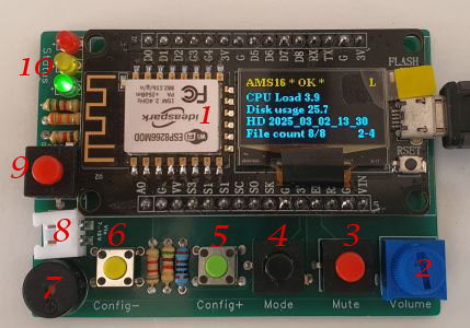
- NodeMCU ESP8266 micro-controller with 128x64 pixel display, a WiFi chip and Mini-USB or USB-C connector
- Volume control
- Mute button
- Mode switch button
- Config + switch
- Config - switch
- Buzzer
- External power supply connector
- External power button
- Status LEDs
Purpose
The purpose of the device is to determine and display the status of AllSky7 cameras:
- Green - Ok
- Yellow - Warning
- Red - Error
The status is determined from the following camera properties:
- Connectivity - can the health interface of the camera be reached
- CPU load - is the CPU load sufficiently low
- Disk usage - is there sufficient disk space
- File - are all camareas recording actively and writing a HD file to disk
When any of these values is outside a certain defined range for a defined time, the status LEDs (10) will switch from green (ok) to yellow (warning) or red (error). In red mode, the buzzer (7) is giving an alert tone. You can control the volume of the buzzer (2), or mute it completely with the corresponding button (3).
Operating Modes
The device has two basic modes, which are select with the mode switch (4).
- Local ("L" is shown in the upper right corner of the display) - The device is scanning for AllSky7 cameras and connects to them via WiFi to determine their state.
- Global ("G" is shown in the upper right corner of the display) - The device connects via WiFi to the Internet, and from there to the AllSky7 camera.
Power Supply
You can power the device either via the USB port or via the external power supply connector (8) with 7..12V. Do not power the device with both sources in parallel, as it may damage the micro controller. You can switch on/off the external power supply with the power button (9).
Startup
When power is supplied, the device will show the welcome screen for a few seconds. The LEDs are blinking and the buzzer is beeping. Next the device is load the configuration (if any is saved in the device) and try to connect to a WiFi.In local mode, the device will scan for all reachable WiFis with SSID AMSxxx and try to connect with a pre-defined password. If the connection is successful, the device will try to load a configuration file from the system. Alternatively, all configuration can later be set manually on the device.
In global mode, the device will try to connect to any of the WiFis which are configured, and connect with the defined passphrase.
When the connection was successful, the device will cycle through all detected WiFis (in local mode) resp. through all configured cameras (in global mode) and determine the status of each camera.
Then the status is displayed for a defined number of cycles, whereby each camera status is displayed for a defined number of seconds. At the end, the loop starts again and the device is cycling through all cameras to determine the status.
Display
In the top yellow line, the display shows the current activity of the device. When the status is displayed, it gives the name of the camera, the status (OK, WARN, ERROR) and the number of cycles that the status has been like this. Below the line you find detailed information. When the status is red, the buzzer is giving an alarm. The current cycle and remaining display time is shown in the lower right corner.
Configuration File
The easiest way to configure the device is via a configuration file config.csv, which needs to be stored on any of the connected cameras in the home folder of user ams. It will be loaded automatically when the device connects to the camera in local mode.
Here is a sample configuration file.
# configuration file for AllSky7 Health Checker
version,1.0
wifi,My WiFi 1,My Passphrase 1
wifi,My WiFi 2,My Passphrase 2
camera,AMS16.allsky7.net,443,/health/txt
camera,AMS35.allsky7.net,443,/health/txt
cpu,5,10
disk,95,99
file,1,2
error,1,3
display,5,3
freq,500
bright,64
Everthing behind a hash sign (#) is regarded as remark and omitted. The following parameters can be configured:
- version: Configuration file version. This is the only mandatory parameter and it must be in the first line of the configuration file, which is not a comment line. The file version must match to the file version of the device firmware.
- wifi - SSID and passphrase of a number of WiFis that the device shall try to connect in global mode
- camera - hostname, port and service URL that the device shall try to connect in global mode
- cpu - minimum CPU load for warning and error level
- disk - minimum disk quota for warning and error level
- file - minimum number of missing recording HD streams for warning and error level
- error - number of occurance of an error, until it is reported as warning or error
- display - number of cycles in which the status is display, before a new status is determined, and duration of status display for each camera
- freq - frequency of the buzzer
- bright - brightness of the LED
Manual Configuration
By pressing both config buttons (5) and (6) in parallel for ~2s (long), you can enter the configuration mode. There you can cycle between the following configuration parameters:
- Check WiFi - all configured WiFis will be displayed and you can decide if you want to keep or delete them (for global mode)
- Get WiFi - all currently reachable WiFis will be displayed, and you can enter a password if you want to add that WiFi to the configuration (for global mode)
- Check camera - all configured cameras will be displayed and you can decide if you want to keep or delete them (for global mode)
- Get camera - you can add the hostname, port, and service URL of new cameras (for global mode)
- CPU Warning - configure the CPU load warning level
- CPU Error - configure the CPU load error level
- Disk Warning - configure the disk quota warning level
- Disk Error - configure the disk quota level
- File Warning - configure the stream recording warning level
- File Error - configure the stream recording error level
- Warning Count - configure the number of consecutive warning states before a warning is displayed
- Error Count - configure the number of consecutive error states before an error is displayed
- Refresh - configure the time, how long a camera status is displayed
- Cycle - configure the number of cycles that all camera stati are displayed, before a new status is determined
- Frequency - configure the frequency of the buzzer
- Brightness - configure the LED brightness
For the configuration items 5 to 16, pressing the config - button (6) shortly will lower the displayed value up to a defined minimum value. Pressing the config + button (5) shortly will increase the displayed value up to a defined maximum values.
Pressing the config - button (6) longer will jump to the previous configuration item, pressing the config + button (5) longer will jump to the next configuration item.
For the configuration items 1 and 3, the config - button (6) will select N and the config + button (5) will select Y. Thereafter you jump automatically to the next WiFi or camera. You will cycle through all WiFis and cameras forever, until you jump to the previous or next configuration item by pressing one of the config buttons longer.
For the configuration items 2 and 4, you can change the current character with the config + and - buttons to the desired value and wait for a short time. Then you can enter the next character, whose start value is copied from the previous one. Use once more config + and - to adjust the value of the character.
If you want to keep the initial character, you have to press the config buttons shortly one after the other, anyway, to start the short countdown for saving the character.
Press both config buttons shortly in parallel to get back to the previous character.
Pressing one of the config buttons longer will save the string and let you edit the previous or next camera or WiFi, unless you press one of these buttons again longer. This will bring you to the previous or next configuration item.
Leave the whole configuration menu by pressing both config buttons longer at the same time.
You can reset (delete) all stored configurations by pressing both button for >10s.
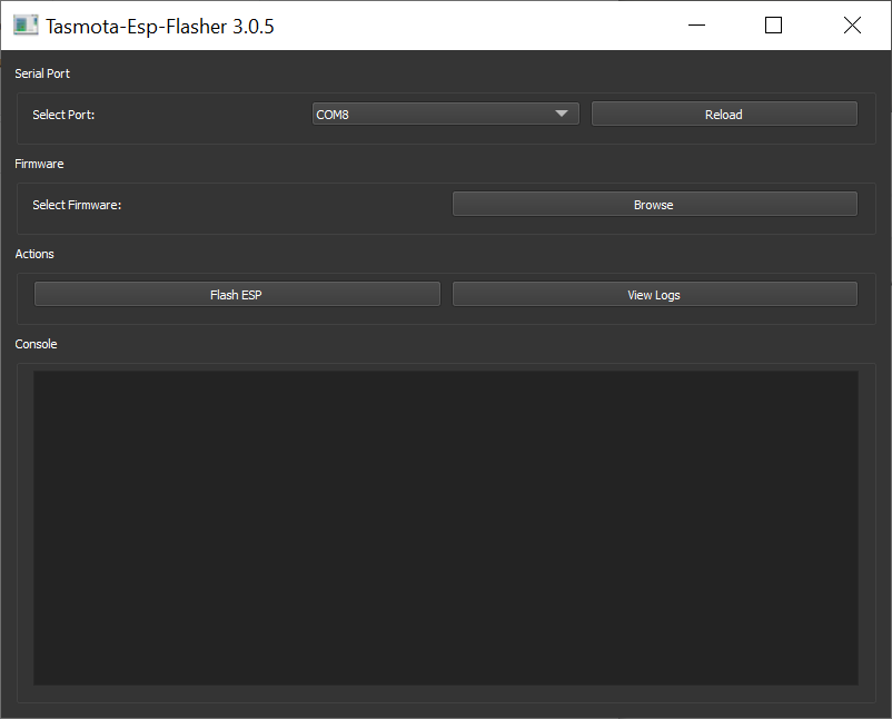
Firmware Upgrade
To upgrade the firmware, you need to download the ESP-Flasher tool to your Windows PC (alternatively directly from Github), and the new firmware file. Connect the device to the USB port of your computer and start the flash tool. Select the COM port of the device and browse for the new firmware file on your PC. Click the flash ESP button to upload the new firmware.